Learning Spanning Tree Protocol with FreeBSD Bridges
Spanning Tree Protocol is a standard protocol for network bridges (layer-two switches) to autonomously find a logical loop-free topology and provide redundancy to the network.
Several variants have been developed since its birth, in which the most common standard is Rapid Spanning Tree Protocol (RSTP). Many managed switches implement the protocol and often enable it by default.
Although it’s quite common in the networking world where I’m living in its perimeter, it’s been something vague and unfamiliar to me for a long time. Maybe it’s because I came from the userland that is above the application layer and gradually went down to lower layers 1. After all, I’m more interested in the higher layers and I haven’t given much attention to the layer one and two.
But recently I noticed that FreeBSD’s if_bridge supports RSTP when I was playing with jails and reading related documents. I instantly felt that this is a good opportunity to learn a litle more about the protocol.
I do know that there are things called network simulators and they are widely used for education. Using some of them would save me some time. But as a UNIX user I want to do it on my own, even if I re-invent the tiny wheel.
This is definitely not a practical usage of FreeBSD 2 but it’s gonna be fun. So I am going to misuse (or abuse) FreeBSD bridges to see how RSTP works!
Please note:
- This article just describes my experience and understadings. It’s never intended to be an accurate and/or concise explanation of Spanning Tree Protocol.
- In the following text, I used the words Spanning Tree, Spanning Tree Protocol and STP mostly to refer to Rapid Spanning Tree Protocol (RSTP).
Preparation
Setting up a Single FreeBSD VM
Basically, all I need is a single FreeBSD host. A virtual machine is best suited because this experiment is inherently dangerous due to possible network loops.
I picked up Vagrant box ‘bento/freebsd-11.2’ to quickly create a VirtualBox vm running FreeBSD 11.2.
(I must confess. My laptop is running Windows 10 and I ran the following commands on cygwin 3.)
HostOS$ mkdir -p ~/vagrant/learnstp
HostOS$ cd ~/vagrant/learnstp
HostOS$ vagrant init bento/freebsd-11.2
HostOS$ vim Vagrantfile
I edited the generated Vagrantfile in order to
- set a memorable name for the vm.
- add port forwarding rule for a web application which visualizes topology.
- enable vm console.
- set a limit on vm’s cpu usage.
This is the modified Vagrantfile.
Vagrant.configure("2") do |config|
  config.vm.box = "bento/freebsd-11.2"
  config.vm.hostname = "learnstp"
  config.vm.network :forwarded_port, guest: 3000, host: 3000
  config.vm.provider "virtualbox" do |vb|
    vb.gui = true
    vb.name = "learnstp"
    vb.customize ["modifyvm", :id, "--cpuexecutioncap", "50"]
  end
end
Then I fired up the vm and logged in via ssh.
HostOS$ vagrant up
HostOS$ vagrant ssh
Building a Simple Network Manually
To grasp the basics of FreeBSD bridge’s STP configuration, I tried first to manually build a simple loop topology with three bridges. All the tasks can be done using a single command, ifconfig(8).
     epair0b +---------+ epair1a
        +----+ bridge1 +----+
        |    +---------+    |
        |                   |
        |                   |
        |                   |
epair0a |                   | epair1b
   +----+----+         +----+----+
   | bridge0 +---------+ bridge2 |
   +---------+         +---------+
         epair2b      epair2a
This topology requires three bridges and three links. I used if_bridge(4) for the former and epair(4) for the latter. As I wrote in another article, I usually use ng_bridge(4) in the netgraph(4) framework but it doesn’t support STP (it has its own loop-detection mechanism, though). Epair is something like a virtual direct attach cable (DAC), which is a network cable with a pluggable tranceiver on either end.
I ran the following commands to create them. Each command printed out a created device name such as bridge0 and epair2a. Note that a single epair provides two pseudo interfaces (e.g. epair2a and epair2b). ifconfig epair create returns only the first one which is suffixed with ‘a’ but there’s also the one with ‘b’ suffix.
$ sudo ifconfig bridge create
bridge0
$ sudo ifconfig bridge create
bridge1
$ sudo ifconfig bridge create
bridge2
$ sudo ifconfig epair create
epair0a
$ sudo ifconfig epair create
epair1a
$ sudo ifconfig epair create
epair2a
As I didn’t have any bridges and epairs before, now I have bridge0, bridge1, bridge2, epair0a, epair0b, epair1a, epair1b, epair2a and epair2b. Interfaces on a system can be listed by running ifconfig with -l flag.
$ ifconfig -l
em0 lo0 bridge0 bridge1 bridge2 epair0a epair0b epair1a epair1b epair2a epair2b
Next, I connected those bridges with epairs. I used ifconfig addm to add member ports (epair pseudo ethernet interfaces) to the bridges.
$ sudo ifconfig bridge0 addm epair0a addm epair2b
$ sudo ifconfig bridge1 addm epair1a addm epair0b
$ sudo ifconfig bridge2 addm epair2a addm epair1b
By default, Spanning Tree Protocol is disabled on bridge member ports. So I used ifconfig stp to enable it.
$ sudo ifconfig bridge0 stp epair0a stp epair2b
$ sudo ifconfig bridge1 stp epair1a stp epair0b
$ sudo ifconfig bridge2 stp epair2a stp epair1b
Now bring up bridges and epairs to see how it goes.
$ sudo ifconfig bridge0 up
$ sudo ifconfig bridge1 up
$ sudo ifconfig bridge2 up
$ sudo ifconfig epair0a up
$ sudo ifconfig epair0b up
$ sudo ifconfig epair1a up
$ sudo ifconfig epair1b up
$ sudo ifconfig epair2a up
$ sudo ifconfig epair2b up
I checked STP topology by running ifconfig for each bridge.
$ ifconfig bridge0
bridge0: flags=8843<UP,BROADCAST,RUNNING,SIMPLEX,MULTICAST> metric 0 mtu 1500
        ether 02:98:96:7c:39:00
        nd6 options=9<PERFORMNUD,IFDISABLED>
        groups: bridge
        id 02:00:90:00:0b:0b priority 32768 hellotime 2 fwddelay 15
        maxage 20 holdcnt 6 proto rstp maxaddr 2000 timeout 1200
        root id 02:00:90:00:07:0b priority 32768 ifcost 2000 port 6
        member: epair2b flags=1c7<LEARNING,DISCOVER,STP,AUTOEDGE,PTP,AUTOPTP>
                ifmaxaddr 0 port 11 priority 128 path cost 2000 proto rstp
                role alternate state discarding
        member: epair0a flags=1c7<LEARNING,DISCOVER,STP,AUTOEDGE,PTP,AUTOPTP>
                ifmaxaddr 0 port 6 priority 128 path cost 2000 proto rstp
                role root state forwarding

$ ifconfig bridge1
bridge1: flags=8843<UP,BROADCAST,RUNNING,SIMPLEX,MULTICAST> metric 0 mtu 1500
        ether 02:98:96:7c:39:01
        nd6 options=9<PERFORMNUD,IFDISABLED>
        groups: bridge
        id 02:00:90:00:07:0b priority 32768 hellotime 2 fwddelay 15
        maxage 20 holdcnt 6 proto rstp maxaddr 2000 timeout 1200
        root id 02:00:90:00:07:0b priority 32768 ifcost 0 port 0
        member: epair0b flags=1c7<LEARNING,DISCOVER,STP,AUTOEDGE,PTP,AUTOPTP>
                ifmaxaddr 0 port 7 priority 128 path cost 2000 proto rstp
                role designated state forwarding
        member: epair1a flags=1c7<LEARNING,DISCOVER,STP,AUTOEDGE,PTP,AUTOPTP>
                ifmaxaddr 0 port 8 priority 128 path cost 2000 proto rstp
                role designated state forwarding

$ ifconfig bridge2
bridge2: flags=8843<UP,BROADCAST,RUNNING,SIMPLEX,MULTICAST> metric 0 mtu 1500
        ether 02:98:96:7c:39:02
        nd6 options=9<PERFORMNUD,IFDISABLED>
        groups: bridge
        id 02:00:90:00:09:0b priority 32768 hellotime 2 fwddelay 15
        maxage 20 holdcnt 6 proto rstp maxaddr 2000 timeout 1200
        root id 02:00:90:00:07:0b priority 32768 ifcost 2000 port 9
        member: epair1b flags=1c7<LEARNING,DISCOVER,STP,AUTOEDGE,PTP,AUTOPTP>
                ifmaxaddr 0 port 9 priority 128 path cost 2000 proto rstp
                role root state forwarding
        member: epair2a flags=1c7<LEARNING,DISCOVER,STP,AUTOEDGE,PTP,AUTOPTP>
                ifmaxaddr 0 port 10 priority 128 path cost 2000 proto rstp
                role designated state forwarding
After struggling with those output, I understood the current topology looks like this.
             Root Bridge
     epair0b +---------+ epair1a       RSTP Port Roles
        +-(D)| bridge1 |(D)-+             (D) Designated Port
        |    +---------+    |             (R) Root Port
        |                   |             (A) Alternate Port
        |                   |
        |                   |
epair0a(R)   Discard       (R)epair1b
   +---------+   |     +---------+
   | bridge0 |(A)X--(D)| bridge2 |
   +---------+   |     +---------+
         epair2b      epair2a
Here, bridge1 had the smallest bridge id (priority/MAC address pair) and was elected as the root bridge. All its member ports became designated ports (D). On bridge0 and bridge2, port closest to the root bridge became root port (R). On the link between bridge0 and bridge2 (epair2), port on the smaller id bridge became designated port (D) and the other became alternate port (A). The alternate port (A) on bridge0 didn’t go into forwarding state and discarded the traffic to prevent loop.
Okay. I could successfully build a Spanning Tree network using command-line. But before going any further, I wanted to do some more preparation.
As you can see, it’s quite tedious to configure bridges with ifconfig. In addition, It’s also hard to see how the physical and logical topologies look like.
To solve those issues, I decided to take some time to write a set of small programs. They are mostly shell scripts to run ifconfig commands in a batch, plus a tiny web application to show bridge topology on a web browser.
Scripting Bridge Operations
The first program I wrote is a thoughtlessly named bridge.sh. It’s just a shell script to run bridge-related operations such as building N-bridge ring or mesh topology, adding a link between bridge A and B, shutting down epairX and showing summary.
With this tiny script, the previously mentioned ring topology can be created by just running a single command.
$ sudo ./bridge.sh ring 3
With the help of additional scripts written in perl, bridge.sh can also summarize the information nicely. This is far better than ifconfig output for this experiment.
(I must confess again. Perl is my favorite scripting language.)
$ ./bridge.sh show
bridge0 32768.02:00:80:00:0c:0b desig root 32768.02:00:80:00:08:0b cost 2000
  epair0a  proto rstp  id 128.7   cost   2000:       root / forwarding
  epair2b  proto rstp  id 128.12  cost   2000:  alternate / discarding

bridge1 32768.02:00:80:00:08:0b [root]
  epair0b  proto rstp  id 128.8   cost   2000: designated / forwarding
  epair1a  proto rstp  id 128.9   cost   2000: designated / forwarding

bridge2 32768.02:00:80:00:0a:0b desig root 32768.02:00:80:00:08:0b cost 2000
  epair1b  proto rstp  id 128.10  cost   2000:       root / forwarding
  epair2a  proto rstp  id 128.11  cost   2000: designated / forwarding
I got almost satisfied with those scripts. But I went on one step further.
Visualizing Topology
Visualization has been a buzzword for a while. I’ve heard a lot about various tools and frameworks to visualize data but I didn’t have any idea where to start.
Long story short, I chose vis.js to visualize topology on web browser, after trying vanilla HTML5 canvas and SVG.js. I also used Mojolicious to serve HTML/JavaScript and feed topology data in JSON to vis.js running on a web browser.
To start the web application, just run the following script. The application starts listening on TCP port 3000.
$ ./run-app.sh
With the port forwarding configuration in Vagrantfile, I can access the application page from the host PC’s web browser with the following URL.
http://localhost:3000/index.html
Now everything is in place.
Seeing How RSTP Works
Electing a Root Bridge in a Network
For each Spanning Tree network, a single bridge is elected as a root bridge. A root bridge is literally a root of a logical tree of network links, which is calculated by bridges in the network.
As the root bridge operates in the core of a network, it’s so important to configure the most appropriate bridge as the root bridge. But how?
In the Spanning Tree network, bridges exchange information using control messages (BPDUs) and automatically elect a bridge with the lowest bridge id value as a root bridge in the network.
A bridge id is a 8 octets (= bytes) value and is made up of two components - a bridge priority and a bridge MAC address. In the previous example of three bridges, strings like ‘32768.02:00:80:00:0c:0b’ are bridge ids. The first part (e.g. ‘32768’) is the bridge priority and the second part (e.g. ‘02:00:80:00:0c:0b’) is the bridge MAC address.
$ ./bridge.sh show
bridge0 32768.02:00:80:00:0c:0b desig root 32768.02:00:80:00:08:0b cost 2000
  epair0a  proto rstp  id 128.7   cost   2000:       root / forwarding
  epair2b  proto rstp  id 128.12  cost   2000:  alternate / discarding

bridge1 32768.02:00:80:00:08:0b [root]
  epair0b  proto rstp  id 128.8   cost   2000: designated / forwarding
  epair1a  proto rstp  id 128.9   cost   2000: designated / forwarding

bridge2 32768.02:00:80:00:0a:0b desig root 32768.02:00:80:00:08:0b cost 2000
  epair1b  proto rstp  id 128.10  cost   2000:       root / forwarding
  epair2a  proto rstp  id 128.11  cost   2000: designated / forwarding
While MAC address is normally unique and not user-configurable, bridge priority is to be configured by administrator.
However, recommended default of the bridge priority is 32768 and FreeBSD’s if_bridge is no exception. So without explicit configuration, bridge priorities could be the same across all bridges in a network. In that case, a bridge with the smallest MAC address is elected as a root bridge. This is effectively a random selection process.
To avoid this unpredictable election process, it is said that network administrators should configure bridge priority of the root bridge candidate to be lower than other ordinary bridges.
Because I didn’t do that in the previous example, all bridges had the same priority value 32768 and bridge1, which happened to have the lowest MAC address among three became the root bridge.
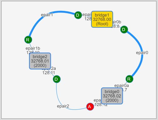
Note that MAC addresses are shortened to 2-digit hexadecimal numbers on the visualization app for brevity. They only represent relative magnitude among the bridges. Actual MAC address can be seen in a popup which appears by putting mouse cursor over a bridge.
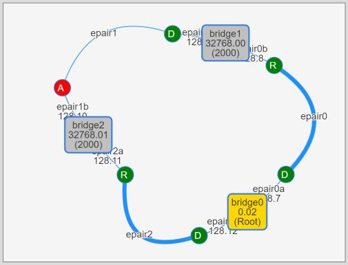
Now let’s try to make bridge0 a root bridge by configuring its bridge priority to a smaller value. Bridge priority can be changed with omnipotent ifconfig command. Here I set bridge0’s priority to the smallest possible value, 0 4.
$ sudo ifconfig bridge0 priority 0
Changeing bridge priority caused another election process and bridge0 became a new root bridge.
$ ./bridge.sh show
bridge0 0.02:00:80:00:0c:0b [root]
  epair0a  proto rstp  id 128.7   cost   2000: designated / forwarding
  epair2b  proto rstp  id 128.12  cost   2000: designated / forwarding

bridge1 32768.02:00:80:00:08:0b desig root 0.02:00:80:00:0c:0b cost 2000
  epair0b  proto rstp  id 128.8   cost   2000:       root / forwarding
  epair1a  proto rstp  id 128.9   cost   2000: designated / forwarding

bridge2 32768.02:00:80:00:0a:0b desig root 0.02:00:80:00:0c:0b cost 2000
  epair1b  proto rstp  id 128.10  cost   2000:  alternate / discarding
  epair2a  proto rstp  id 128.11  cost   2000:       root / forwarding
It must be undesirable to change bridge priorities carelessly in a production network but it’s okay in this experimental network. However, if you want to configure a specific bridge to be a root bridge when creating a topology, you can use bridge.sh script’s -R (root) flag.
For example, you can generate the same 3-bridge topology with the first bridge (e.g. bridge0) being a root bridge by running the following command. -R 1 specifies that the first bridge to be a root bridge. The command sets its priority to 0 while leaving other bridge’s priorities at default value of 32768. Without -R flag, all bridges will have default priority values.
$ sudo ./bridge.sh ring -R 1 3
Selecting a Root Port on Each Bridge
For each non-root bridge, a single root port is selected based on its distance (cost) to the root bridge. Basically, a port closest to the root bridge becomes the root port on a bridge.
To calculate the distances, every RSTP-enabled port has a property called port pathcost. By default, it is automatically configured according to its link speed.
In the previous example, all ports (epairs) have a cost of 2000, which is the default value for 10Gbps links! Running ifconfig on one of the epair interfaces let me confirm that they were configured as 10Gbase-T interfaces.
$ ifconfig epair0a
epair0a: flags=8943<UP,BROADCAST,RUNNING,PROMISC,SIMPLEX,MULTICAST> metric 0 mtu 1500
        options=8<VLAN_MTU>
        ether 02:ff:00:00:07:0a
        hwaddr 02:ff:00:00:07:0a
        inet6 fe80::ff:ff:fe00:70a%epair0a prefixlen 64 scopeid 0x7
        nd6 options=21<PERFORMNUD,AUTO_LINKLOCAL>
        media: Ethernet 10Gbase-T (10Gbase-T <full-duplex>)
        status: active
        groups: epair
With this (all ports have pathcost 2000) in mind, let’s look at each port’s distance to the root bridge (it is called the port’s root pathcost).
On bridge1, epair0b’s root pathcost is 2000 because bridge1 considers that the cost of the link attached to epair0b interface is 2000 and it is the only link required to reach the root bridge (bridge0). On the same bridge, epair1a’s root pathcost is 4000 because there are two links (epair1 and epair2) between the interface and the root bridge thus the total root pathcost of epair1a is equal to 2000 + 2000. So, epair0b becomes the root port on bridge1 because it has the smallest root pathcost on the bridge.
On bridge2, epair2a is selected as the root port in the same way.
On each non-root bridge, a port closest to the root bridge becomes the root port on the bridge. Very simple.
But what if a bridge has more than one ports with the same root pathcost?
There could be two cases for this. The first one is the case where a single bridge is connected to two or more other bridges and those bridges have the same root pathcost.
Another case is that a single bridge has two or more links with the same pathcost to another bridge.
There’s no such situations in the previous example. So I tried to create them.
The first case can be generated by adding a new bridge and connect it to both bridge1 and bridge2. To achieve this, I ran the follwoing commands.
sudo ./bridge.sh ring 1
sudo ./bridge.sh connect bridge1 bridge3
sudo ./bridge.sh connect bridge2 bridge3
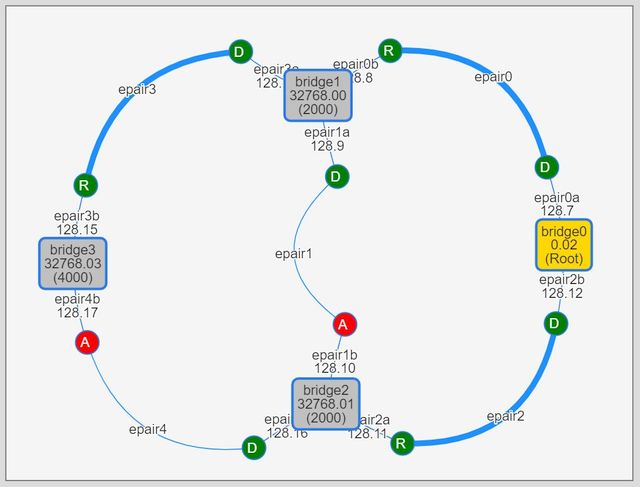
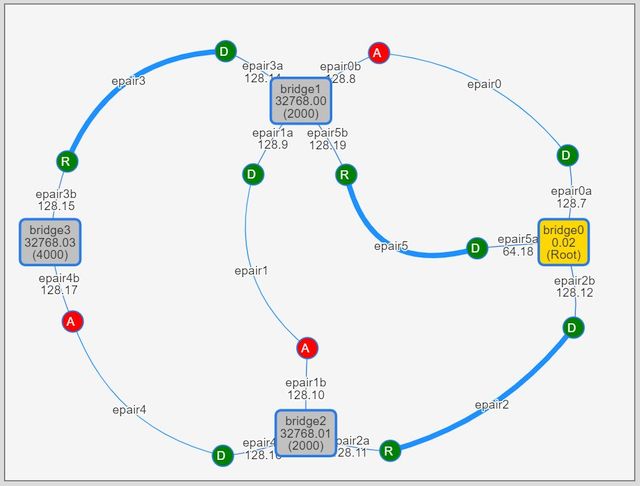
Those commands added bridge3 and linked it to bridge2 and bridge3 with newly created epair3 and epair4 respectively. Here bridge3 has two ports, epair3b and epair4b, which have the same root pathcost of 4000.
If a bridge has multiple ports with the same least root pathcost, it choose a port connected to a neighboring bridge with the lowest bridge id as the root port. In this case, bridge3’s neighbors are bridge1 (shortened id: 32768.00) and bridge2 (shortened id: 32768.01) and bridge1 has the lower bridge id. bridge3 chose epair3b as the root port because it is connected to the lowest id neighbor, bridge1.
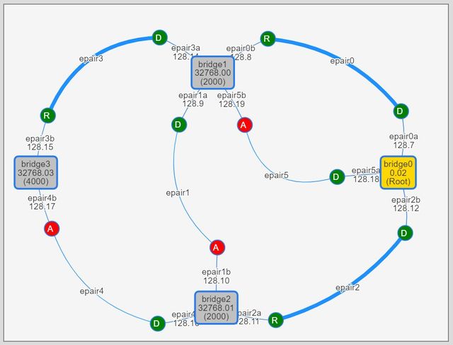
The second case can be observed by adding a parallel link between bridge0 and bridge1. I ran the following command.
sudo ./bridge.sh connect bridge0 bridge1
This command added a new link epair5 between bridge0 and bridge1. Now bridge1 has two ports with the same least root pathcost, epair0b and epair5b. This time, both ports also has the same neighbor, bridge0.
If a bridge has multiple ports with the same least root pathcost and the same neighbor, it choose a port whose neighbor port has the lowest port id. A port id is comprised of a port priority and a port index (number). As with the bridge id, port priority can be user-configurable while port index is determined by the system. Recommended default value of the port priority is 128. On the visualization app, port ids are shown like 128.7 where 128 is a priority and 7 is a port index.
In this example, epair0b’s neighbor epair0a’s port id is 128.7 and epair5b’s neighbor epair5a’s port id is 128.18. Therefore, bridge1 continued to use epair0b as the root bridge even after epair5a was added as a parallel link to bridge0.
If you want bridge1 to use epair5b as its root port, you can set its neighbor port’s priority to lower value. I tried this by running the following command 5.
sudo ifconfig bridge0 ifpriority epair5a 64
Now epair5b’s neighbor epair5a’s port id was changed to 64.18 while epair0b’s neighbor epair0a’s port id is unchanged at 128.7. So bridge1 changes its root port from epair0b to epair5b.
Determining Designated and Alternate Ports
After selecting root ports, each bridge selects designated ports out of the remaining ports. I think a designated port is somewhat like a gateway in IP terminology. That is, a designated port is a port on a link through which another port on the link can reach the root bridge with the minimum root pathcost. I was confused with the distinction between selection processes of root port and designated port but in summary:
- Root port is selected according to the distance out FROM the port.
- Designated port is selected according to the distance THROUGH the port and the bridge it belongs to.
On each link, a port on a bridge whose root port has the lowest root pathcost becomes the designated port on that link. Then remaining ports which aren’t selected as root or designated port become the alternate port 6 and block traffic to prevent loop.
Let’s look at an earlier example again.
All ports on the root bridge (epair0a and epair2b) become designated ports because those ports are apparently closest to the root bridge on their links (epair0 and epair2).
On the link between bridge1 and bridge2 (epair1), epair1a on bridge1 and epair1b on bridge2 have the same root pathcost of 2000. In this case, a port belonging to the bridge with the lowest bridge id becomes the designated port on the link.
Here bridge1’s (shortened) id is 32768.00 while bridge2’s is 32768.01, thus on epair1 link epair1a on bridge1 became the designated port and epair1b on bridge2 became the alternate port.
Reacting to Topology Changes
Next I wanted to see how RSTP reacts to topology changes.
For this, I wiped the previous topology and created 4-bridge full-mesh topology with the following commands.
$ sudo ./bridge.sh destroy-all
$ sudo ./bridge.sh mesh -R 1 4
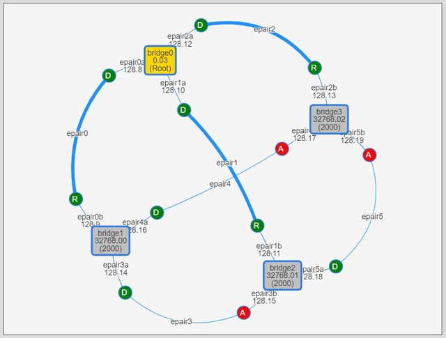
Here bridge0 became the root bridge. Other bridges selected their ports directly connected to the root bridge (epair0b on bridge1, epair1b on bridge2 and epair2b on bridge3) as the root ports.
On each of the other links (epair3, epair4 and epair5), ports on both ends have the same pathcosts through its bridge’s root port. So on each of those links, a port on the lowest id bridge became the designated port and another port became the alternate port.
First, I brought down epair0 between bridge0 and bridge1.
$ sudo ./bridge.sh linkdown epair0
As bridge1’s root port was changed from epair0b to epair3a, a path to the root bridge (bridge0) from bridge1 was now bridge1 - bridge2 - bridge0 and its pathcost was increased to 4000.
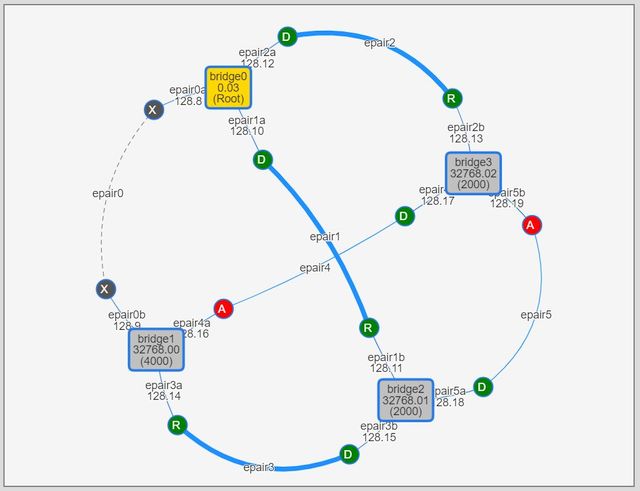
Bridge1 had two candidates for the new root port, epair3a and epair4a. Because both had the same root pathcost of 4000, neighbor bridge ids were used to determine the root port thus epair3a (neighbor bridge id was 32768.01) was selected over epair4a (neighbor bridge id was 32768.02).
Now let’s generate an exterme situation. I ran the following commands to do this.
$ sudo ./bridge.sh linkdown epair2
$ sudo ./bridge.sh linkdown epair5
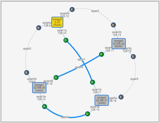
Three out of six links were down now and logically four bridges were connected in line like bridge0 (root) - bridge2 (cost 2000) - bridge1 (cost 4000) - bridge3 (cost 6000).
Very Brief Conclusion
I’m sure that there’s a lot more to learn, but visualizing FreeBSD’s real bridge operations greatly helped me understand fundamentals. For a text-oriented UNIX user like me, this was a really great lesson!
References
-
Vagrant Cloud - Vagrant box bento/freebsd-11.2
https://app.vagrantup.com/bento/boxes/freebsd-11.2 -
FreeBSD Manual: ifconfig(8)
https://www.freebsd.org/cgi/man.cgi?ifconfig(8) -
FreeBSD Manual: if_bridge(4)
https://www.freebsd.org/cgi/man.cgi?if_bridge(4) -
FreeBSD Manual: epair(4)
https://www.freebsd.org/cgi/man.cgi?epair(4) -
FreeBSD Handbook: Advanced Networking / Bridging
https://www.freebsd.org/doc/en_US.ISO8859-1/books/handbook/network-bridging.html -
Cygwin
https://cygwin.com/ -
vis.js - A dynamic, browser based visualization library
https://visjs.org/ -
SVG.js - The lightweight library for manipulating and animating SVG
https://svgjs.com/ -
Mojolicious - Perl real-time web framework
https://mojolicious.org/ -
GitHub: genneko/learnstp - Small programs to help experiment Spanning Tree Protocol with FreeBSD if_bridge
https://github.com/genneko/learnstp
-
I can clearly recall the excitement when I sent an email by directly talking to a SMTP server using telnet client for the first time. ↩︎
-
It’s also not specific to FreeBSD. The same experiment must be possible with any other operating system which supports STP bridges. I just used my favorite OS. ↩︎
-
I’m also testing WSL (Windows Subsystem for Linux). It’s handy sometimes but it’s not enough to be used as true UNIX/Linux environment. So I’m still using cygwin as a primary command-line workspace on Windows. ↩︎
-
Actually a bridge priority can be only a multiple of 4096 between 0 and 61440. ↩︎
-
A port priority can be only a multiple of 16 between 0 and 240. ↩︎
-
There’s also a port role called “backup port”. It’s only used when multiple ports on a bridge are connected to the same shared media like a repeater hub (non-switching hub). In such a case, ports with non-optimal port id become backup port. I could produced this situation by attaching both ends of a epair to the same bridge but I think it’s rare to use such configuration so I didn’t go deeper on this subject. ↩︎